The devil is in the acoustic details (part two): Acoustic caulking - wall joints
- Post Date
- 05 May 2022
- Read Time
- 5 minutes

In the first installment of our series on the Devil is in the Acoustic Details, Brad Pridham discussed two important decisions for metal stud acoustic wall assemblies:
1) the stud gauge; and,
2) the stud spacing.
Armed with this information, you’ve selected the appropriate stud gauge, width, and spacing to meet serviceability criteria (deflection and durability), and sound isolation performance (e.g., STC). So are we good to go, or are there other potential pitfalls out there to reduce the assembly sound isolation performance from that targeted?
Recall from Part 1 that oversight of seemingly small but absolutely critical details have huge effects on meeting targeted privacy or sound isolation performance of metal stud/ GWB assemblies. In my many years of providing guidance on sound isolation in partitions, one of the more important overlooked details is the presence of gaps, holes or other openings in the partition. In this second installment, I discuss one gap in particular – the joint between the floor at both the top and bottom of the wall. Other commonly found gaps and openings will be discussed in future posts.
Mind the Gap
“Mind the gap” is as important to the sound isolation performance of wall assemblies as it is to the safety of London Underground riders (or riders on other transit systems in many parts of the world). In both cases, not paying attention to the gap(s) usually result in noise, potential pain and can be costly!
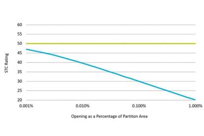
Even small gaps can drastically reduce the sound isolation performance of an acoustical assembly. A small gap permits sound to be readily transmitted just as easily as light in a corridor is transmitted through a cracked door or under-door gap, to a darkened room. A small opening of less than 1% of the area in a partition reduces an STC 50 rated assembly by as much as 30 dB. See Figure 1.

Figure 1: Degradation of Partition Sound Isolation (STC) Rating with Gaps.
Consider the case of a GWB wall assembly that is normally rated at STC 50, but has a ½” (12mm) gap between the floor and the wall at both the top and bottom of the wall. For a 14 ft high wall assembly (floor- underside of floor), these seemingly insignificant gaps represent a mere 0.6%, of the total area (i.e., 1” out of 168”) but degrades the sound isolation to STC 22. A reduction of 28 points!
There’s a Hole in the Bucket
The obvious solution to a leaky hole or gap is to plug it, but how? Some plugs don’t work as well (and still leak), some come with side effects – messy, hard to install, and some degrade over time with holes re-emerging.
A non-hardening acoustical caulking is recommended as the appropriate sealant. Acoustical caulking used to be a black butyl based compound, and was quite frankly messy. Not exactly the material you would want near completed finishes. However, there are now a large number of non-hardening (usually silicone based) sealants that don’t suffer from these shortcomings. Today’s options include combined smoke/fire / acoustic intumescent non-hardening products that can serve multiple purposes.
Applying Acoustic Caulking For Best Performance
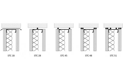
While some caulking is better than no caulking, there is a substantial range of sound isolation performance resulting depending on how the caulking is applied. For example, a common mistake is to apply a bead of caulking only to the footer or header track. This results in significant sound flanking at the GWB gap and through the header or footer track. Controlling this flanking path requires that the gap be sealed at the GWB and floor interface. Figure 2 illustrates performance improvements based on the amount and location of caulking applied.

Figure 2: Effect on sound isolation of various caulking application methods. The STC rating of GWB partitions is significantly affected by gaps and the effectiveness of sealing (caulking) at the base /header tracks. Tests conducted on an STC 51 wall with various caulking conditions illustrate the degradation in performance, with poor acoustic seals. Per Reference 1.
Another common mistake is to apply caulking only to the base (footer track), arising from a misconception that the ceiling will provide the necessary sound isolation. This is only true where the ceiling is itself designed to provide sound isolation matching that of the wall. This does not usually occur for finished lay-in tile ceilings and even if there is a hard GWB ceiling, penetrations for lighting, HVAC ductwork and other services reduce the sound isolation effectiveness of the ceiling.
Parting thoughts
Based on the above, some key takeaways to consider for your next project are:
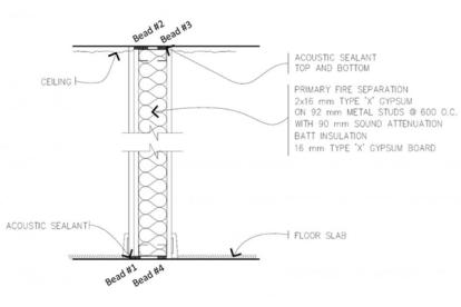
1) Provide details showing where non-hardening acoustic caulking is to be applied. Caulking should be applied to the GWB/floor joint for every sheet of GWB per illustration in Figure 2 and for critical applications, apply to the track as well. Avoid details such as that shown in Figure 3.

Figure 3: Example from forensics project work illustrating inconsistencies and poor details for the application of acoustical caulking. Caulking Bead 1 provides good sound isolation. Caulking Bead 2 is marginal. Caulking Beads 3 & 4 applied to the track only, provide poor sound isolation. Overall, this wall tested 10- 15 STC points below its design value.
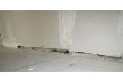
2) Even small holes/ gaps can seriously affect the performance of the wall assembly. Field reviews during construction administration are important to achieving the desired performance – even when properly detailed in the design documents. Caulking should be placed where it can be visually inspected. Any debris under the base/header tracks and in the joint should be cleared to avoid widening the gap and impairment of effective seals. See Figure 4 for an example of improper treatment.

Figure 4: Common examples of poorly applied acoustic caulking illustrating a) rigid gypsum compound used to seal the gap b) caulking applied to the track and not the GWB/floor joint c) large gaps between the GWB sheet and floor, and d) construction debris impairing seal.
3) Keep gaps as small as possible. We recommend placing the inside layer of GWB with a maximum ¼” gap top and bottom, then caulk. Place caulk bead at top (or bottom) then press GWB into caulk. See Figure 4.
Reference:
[1] Doelle, L. (1972) Environmental Acoustics, McGraw-Hill Book Company, 1972.
Recent posts
-

-

Understanding sound flanking: Fire alarm speaker cable conduits in multi-family buildings
by Neil Vyas
View post -
